This chapter presents the
procedures for determining selected properties of elements and a
description of their interpretation related to the method of
displaying a drawing, saving as a image file, printing on a printer
and plotting on a plotter.
The user can place graphic primitives on one of the selected drawing layers. You can easily group different parts of a drawing using layers. Each layer can contain drawing elements that are related to each other in some way. This allows you to control the way of displaying groups of objects, facilitates editing operations, and finally organizes the drawing and speeds up drawing elements with different attributes of color, thickness or line type.
Layers can be imagined as overlapping sheets of transparent foil on which elements are drawn. AlfaCAD allows you to use 255 drawing layers with names set individually by the user or predefined in a prototype drawing with the possibility of changing them.
The order in which objects are drawn is independent of their arrangement in layers. The layer number (and associated name) is an attribute of each feature. This attribute can be changed at any time, which allows you to freely move objects from one layer to another.
The layer handlers allow any combination of layers to be displayed simultaneously. Layers and related parameters are an integral part of the drawing and are stored in the drawing file.
Each layer is assigned a default line color, type, and thickness. These parameters can be changed at any time.
Each object is assigned a color number between 1 and 255.
In order to facilitate the exchange of drawings between different graphics programs, the numbers of the first 16 colors have the standard meanings shown below:
red
yellow
green
turquoise
blue
crimson
white
dark gray
dark red
brown
dark green
dark turquoise
dark blue
dark crimson
Gray
black
The other colors (17...255) are defined according to the DAC-Normal palette.
The graphic primitive's color attribute can be changed at any time in edit mode, as can the layer number.
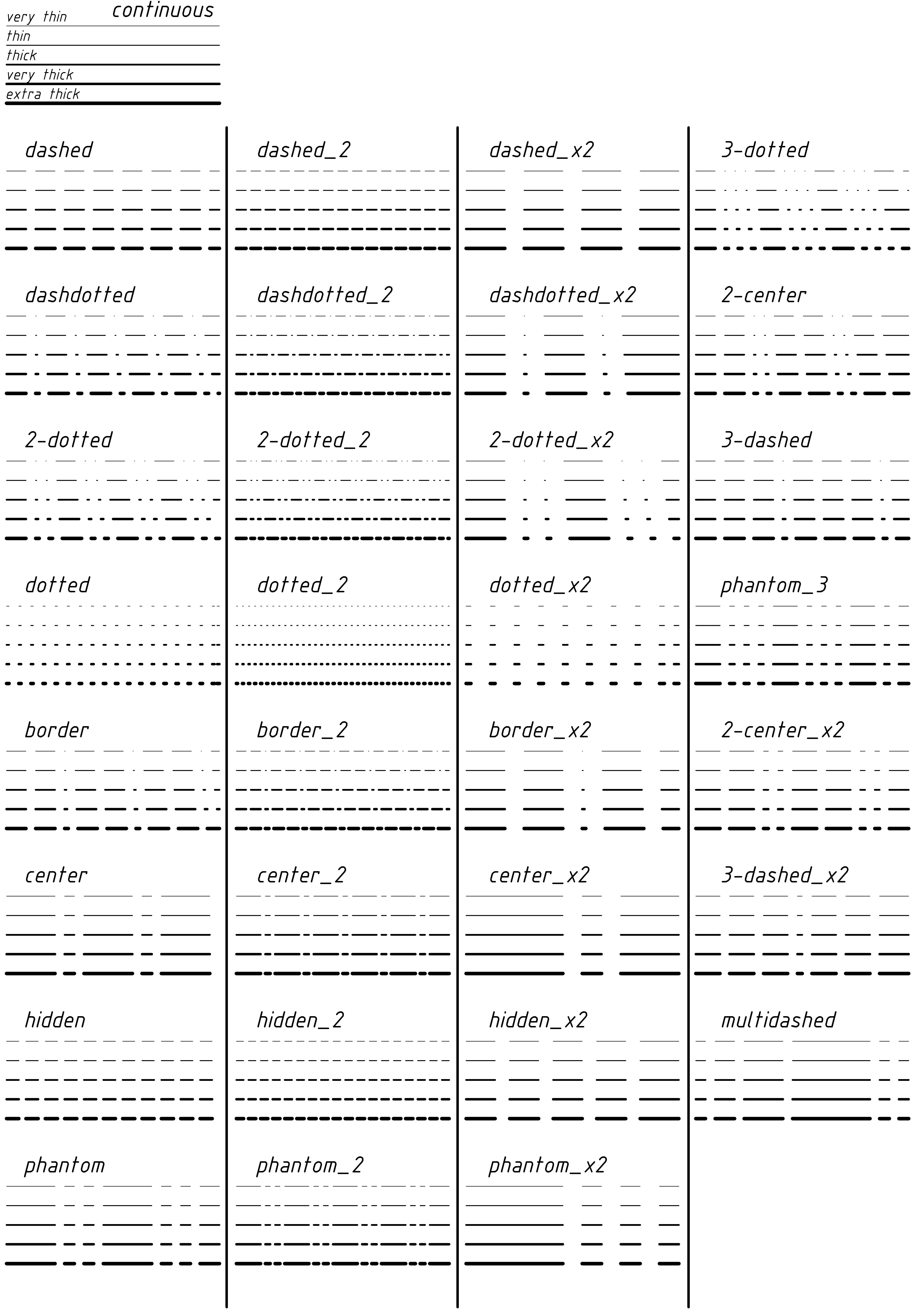
Each line, polyline, circle, arc, polygon, curve, etc. is assigned one of the 5 available line weights (thicknesses):
very thin
thin
thick
very thick
extra thick
Line widths are distinguished on the computer screen. A very thin line and a thin line are displayed as single points apart. A thick line is one point thick on the monitor, a very thick line is three points thick, and the thickest line is 5 points thick. Such a structure of the lines on the monitor allows for a satisfactory artistic effect with limited graphic possibilities of the screen.
With screen scales <1 , the line thicknesses are reduced in steps, which allows for a more faithful presentation of the drawing. With a screen scale > 1, the thickness of the displayed lines is not modified.
Each line thickness on the screen is assigned an appropriate line thickness expressed in millimeters when printed on a printer.
In the case of drawing a drawing with a classic vector plotter (rarely found today), each line thickness can be assigned a specific group of plotter pens. A specific pen in this group is assigned one of the line colors. This allows you to keep the appropriate thickness of lines when plotting on the plotter (by selecting pens of the appropriate thickness) as well as preserving the colors (by selecting colored pens). For a single-color plot, the color attribute allows you to increase the number of line thicknesses available.
The method of defining the line thickness on the printout is described in the following chapters.
The thickness of the lines on the printout is related to the 1: 1 print scale. If the printout is performed in the compression mode (scaling to the paper width), the line thickness is appropriately modified to the print scale.
The line thickness attribute of a graphic primitive can be changed at any time in edit mode, as well as the color and number (name) of the layer.
Each line, polyline, circle, arc, polygon etc. is assigned one of the 32 available line types , including the first 5 basic types shown on the image (together with all 5 line widths)
Lines marked ....._ 2 are variants
with a pattern twice smaller than their equivalents, with markings
......_ x2 are variants with a pattern twice larger.
The line
types (for all weights) are shown in the LINIES32EN.ALF drawing
included in the package.
The types of lines are distinguished on the computer screen in a way that allows to obtain the most faithful representation at the screen scale 1: 1.
With screen scales <> 1, the line pattern is not scaled. This fact does not allow for a faithful presentation of the drawing in different screen scales, but in return, editing operations are performed very quickly, thus compensating for the imperfections of a monitor with a finite graphic resolution.
An important feature of the line type attribute is that the scale of the line type is not scaled up in editing operations. Any part of the drawing can be scaled, but all lines will retain their proportions expressed in the scale of the printout on a printer or plotter, which is consistent with the general principles of making a technical drawing.
Each line type has a line pattern defined in the configuration parameters in the form of a sequence of segments, points and gaps between segments and points, expressed in millimeters on a 1: 1 scale printout. If the printout on a printer or plotter is made in the compression mode (or in the scale <> 1 ), the line pattern is scaled.
The graphic primitive's line type attribute can be changed at any time in edit mode, as can the thickness, color, and layer number.
Each layer has the following properties:
Layer name
The name of the layer allows it to be identified in various editing functions. The name can be up to 16 characters long. It is recommended to use mnemonic names, eg WALLS, AXES. The layer name can be changed many times during the drawing session.
Visibility
A layer can be visible or invisible (hidden). Only the visible layers are displayed, printed, saved as image file, or plotted. Hidden layers remain part of the drawing, but you cannot edit them. In order to edit objects of a given layer (e.g. move, copy, etc.), turn on the visibility of this layer.
Line
color
The layer is related to the default line color that will be used to draw newly drawn objects. The default line color may be different for each layer and it can be defined in the layer parameters editing window or by using the / Parameters // Color / function, which is an option of the auxiliary menu. In the edit window it is possible to edit the default line colors for many layers simultaneously. In the function / Parameters / it is possible to change the color of the current line, which is equivalent to changing the default line color of the current layer. Changing the current layer is the same as changing the current line color to match the default line color of the currently selected layer.
Line
thickness (width)
The layer has a default line thickness that will be used to draw newly drawn objects. The default line thickness may be different for each layer and it can be defined in the layer parameters dialog window or by using the / Parameters // Line thickness / function, which is an option of the auxiliary menu. In the function / Parameters / it is possible to change the current line thickness, which is equivalent to changing the default line thickness of the current layer. Changing the current layer is the same as changing the current line weight corresponding to the default line weight of the currently selected layer.
Line
type
The layer has a default line type that will be used to draw newly drawn objects. The default line type may be different for each layer and it can be defined in the layer parameters edit window or using the / Parameters // Line type / function, which is an option of the auxiliary menu. In the function / Parameters / it is possible to change the current line type, which is equivalent to changing the default line type of the current layer. Changing the current layer is the same as changing the current line type to match the default line type of the currently selected layer.
Editability
The editable attribute allows you to control the editing of individual objects (moving, copying, etc.). If editing of a given layer is turned off, even though the objects in the layer are displayed (if the layer visibility is turned on) these objects are not edited. If the visibility of a layer is turned off, the layer's objects are also not edited. The value of the edit attribute does not affect how the drawing is printed on a printer, saved as an image file, or plotted.
Localizability
The point location ability attribute in relation to the feature of a given layer allows you to control the point location method in the / Point / option in auxiliary menu. If the “snap” attribute for a layer is turned off, the features of that layer are not included in the point localization procedure. This property makes it easier to create a drawing, e.g. in situations requiring drawing installation elements (fittings) with reference to a previously drawn network of pipes, against the background of a construction base placed on separate layers, the visibility of which is necessary, but due to the compaction of the drawing, taking into account the objects of this layer in the point location procedure is undesirable.
The drawing editor highlights the current layer, color, thickness and line type. The “current” layer is the layer on which new elements are drawn. The default parameters for the currently selected layer determine such features of the drawn objects as color, thickness and line type, however, those parameters can be changed at any time, or in layers configuration dialog window, or in / Parameters / of auxiliary menu.
In the top line of the screen, information about the current layer is constantly displayed, including the number of the layer, its name and attributes in the form of anagrams:
+ V -V visible / invisible layer + E -E possible / impossible editing, + P -P possible / impossible location of the point.
A given layer is selected as the current layer in the layer parameters editing window (option / Layers / auxiliary menu) using the switches located on the left side of the layer names edit fields.
The invisible layer cannot take the current layer attribute.
Apart from the number, name and attributes of the current layer, in some drawing functions and editing functions, the top line displays information about:
the current line thickness and type
current font and text height
A square painted in the color of the current color of the current layer is constantly displayed in the upper left corner of the screen.
When you start editing a new drawing, AlfaCAD adopts the configuration of the layers and their parameters based on the prototype drawing. If the prototype drawing does not exist, the program automatically creates layer 1 named "0", assuming by default the other parameters ("White" color, "Thick" line thickness, "Continuous" line type). Layer "0" gets the attribute of the current layer.
The parameters of layers, assumed by default or based on a prototype drawing, may be changed during the drawing execution.
Layer parameters are edited in the layer attributes dialog box, accessible from the auxiliary menu (option / Layer / ).
It is possible to create a new layer or change the parameters of existing layers at any time, regardless of the currently implemented function of drawing objects, editing existing objects, setting drawing sheet parameters, etc.
Changes to layer attributes are
accepted by selecting the <OK>
button.
To cancel
changes and return to the previously defined layer setup, press <Esc>
button .
Pressing <New> button in the dialog box, allows you to create a new layer. The new layer takes the following default parameters:
Layer name - ""
Visibility - +
Editability - +
Localizability - +
Color - White
Line thickness - Thick
Line type - Continuous
To select a particular layer as the current layer press appropriate radio button at the front of the layer name. The current layer must be the visible.
The switch on the right side of
the layer name edit line is used to change the visibility attribute
of a given layer.
The visibility attribute must be active for the
current layer.
Visibility of all layers can be turned on or off using the buttons at the bottom of the dialog box.
The second switch on the right side of the edit line of the layer name is used to change the "editability" attribute of a layer.
Regardless of the value of an edit attribute, if a layer is invisible, it cannot be edited too.
Current layer can be also editable or not.
The editability of all layers can be turned on or off with the buttons at the bottom of the dialog box.
The third switch on the right side of the layer name edit line is used to change the "Localizability" attribute (location of a point in relation to an object) of a given layer.
The change of the location attribute value is done similarly to the visibility attribute.
Regardless of the value of this attribute, if a given layer is invisible, the objects of this layer cannot be pointed in localization functions (it is not possible to indicate invisible object).
The point location of all layers can be turned on or off with buttons at the bottom of the dialog box.
A necessary condition for editing objects (e.g. moving, copying, etc.) is the generally active attribute of the visibility of the layer in which the objects to be edited are placed.
The second necessary condition is the active editability attribute of this layer, because otherwise it will not be possible to indicate objects on which the editing operation is to be performed. In a special situation, which is selecting the objects to be edited by selecting the / Block // Last block / auxiliary menu option, the group of objects that was previously edited may - as a result of changing the layer parameters - currently appear on the invisible layer or in a layer with the attribute turned off edibility. If, as a result of selecting the "last block", objects located in the invisible layer are selected, these objects will remain selected (so they can be edited), but an appropriate message will be displayed informing that the indicated objects lie in the " -V layer" (invisible layer). If, however, these objects lie on a layer with the editability turned off, a message will be displayed stating that you are trying to select layer objects" -E " (the layer with the editability turned off) and the " last block " is ignored.
The decision to continue the editing procedure in the event of the occurrence of the "last block" objects on the invisible layer belongs to the user, and the effect of performing the editing function on these objects will not be visible on the screen until the visibility attribute of the layers is changed.
Blocks (created by the user, dimension blocks, hatch blocks, etc.) are edited in a similar way when some elements of the selected block lie on an invisible layer or a layer with the edit attribute turned off.
Objects are copied with their position in layers, I.e. regardless of the current layer, the object copy remains in the layer in which the master object is located. After the copy function is finished, a given object can be transferred to any layer using the edit function / Change /.
If the whole group of recently copied objects is to be transferred to another layer, you can use the / Block // Last block / auxiliary menu option when selecting these objects.
Blocks read from files in the function / Block // Import / are placed on the current layer or on the original layers. It depends on setting the "Fixed layer" parameter in the / Block / function. As before, in order to move the imported block to another layer, you can use the / Last block / option because the last imported block, just like in the case of editing functions, gets the "last block" attribute.
In order to transfer individual block elements to different layers, the block should be exploded (/ Edit // Explode /) and then - after selecting the appropriate objects - transfer them to another layer using the edit function / Change /.
In the auxiliary menu / Measure / there is a function / property List / which allows to obtain detailed information about the indicated object, i.e .:
OBJECT TYPE
layer
Colour
line type
line thickness
start point, end point, angles, radius, and others appropriate to the type of object
length, perimeter, and area as appropriate for the type of object
font name and other parameters for texts
possible name of the block to which the object belongs
After displaying the parameters, the program waits for selecting one of the menu items, which is a value saved in the notebook, for later use, or the {ESC} key.
Information is shown in tips frame form, next to each parameter position in the information menu. Selecting any parameter from the information menu effects copying shown value in tips frame into the notepad, to be used in further text editing or numeric calculations.