Drafting standards provide for
hatching or filling closed areas with a specific pattern. The hatch
pattern allows you to specify the material from which a given element
is made, give the appropriate texture to architectural elements, show
shadows, etc.
AlfaCAD offers the function of hatching and filling
areas with a pattern with the possibility of defining your own
patterns.
Each hatch pattern is a composition of line segments of specified length and angle. Line segments, continuous or consisting of shorter sections, can compose any pattern. The defined hatch pattern is repeated many times, creating a block that fills the exact area within its closed boundaries.
The program automatically groups the segments that make up the hatch pattern into a block. This allows you to delete the entire hatch pattern (e.g. in the case of an incorrectly selected pattern, scale, etc., or an incorrectly specified hatch area).
The hatch pattern block is subject to the same editing functions as other user-defined blocks (using the / Block // Group / or / Block // Export / function ). In this block, you can (without breaking it into primitives) cut out line fragments, cut lines or lengthen them, etc.
If you need to remove a portion of
a fill block, you can do so after exploding the block. Fill blocks
are blocks of an undefined type, so they are not added to the list of
blocks available in the function / Block // List /.
Although a
hatch pattern can consist of lines and points, point are represented
by short line segments, and the block is always generated on the
current layer using solid lines of the current color and thickness.
Hatching may fill a closed area, the boundaries of which are determined by segments, arcs, circles, discs, polylines (including ellipses, rectangles), curves, sides of polygons, edges of areas and traces, fictitious text boundaries.
Indication of objects limiting the hatch area is carried out in the same way as selecting objects in editing functions, e.g. /Move/, /Copy/ etc.
Objects that make up hatch boundaries can meet at their endpoints or cross each other. The points of intersection of objects mark the vertices of any irregular polygon (convex or concave).
The bounded area need not be coherent, so inside the closed area there may be other closed areas forming the inner boundaries of the hatch area.
The closed area can be created by practically any number of objects or their fragments. In the case of very complex structure of enclosing boundaries, the area can be divided and filled with fragments. Regardless of the complexity of the pattern, each piece of fill will match the others, creating a visually continuous pattern thanks to the identical base point coordinates of the pattern for each piece.
Any text can be an object that delimits closed area boundaries. It defines an area formed by an imaginary text edge ("frame"). If the text (or rather its frame) lies within another closed area, indicated as the hatching area, and that text is also selected as the bounding object, the text will be "wrapped" in a hatch pattern while remaining readable.
After indicating objects that limit the hatch area, you should indicate the inner point of this area. This point clearly defines which of the areas (in the case of a non-coherent area) is to be filled.
The program allows you to select (for a non-coherent area) only one point inside an enclosed area. If there is a need to fill several areas limited by the same set of edges and the same or a different hatch pattern, the procedure can be performed multiple times using the / Last block / option when redefining the objects delimiting the area, indicating each time different internal point.
The hatch function is based on the following parameters defined in the auxiliary menu / Hatching / :
/ Pattern /
/ Rotation angle /
/ Scale /
/ Base point /
/ Indicate base point /
/ Distance /
Standard patterns are always available, and they do not need to be specifically defined:
////////////////
- hatching with lines parallel to the
given direction
XXXXXX
- hatching with lines parallel and
perpendicular to the given direction
Angle, scale, line thickness and color can be changed, like In any other pattern.
Other, more complex patterns are pre-defined (around 70 patterns) and can be defined by user. AlfaCAD doesn't limit the number of user-defined patterns.
The included (pre-defined) patterns are demonstrated on the drawing HATCH.ALF attached to the installation package. These patterns can be freely modified by the user, extended and supplemented.
Defining Hatch Patterns (Patterns)
Modifying and defining hatch patterns (patterns) requires some knowledge, practice, patience and use any text editor.
Hatch pattern definitions are placed in the configuration file ALFACAD.INI in the group of variables named [Patterns] .
Each pattern definition has the same format: a header line and one or more description lines .
The header line looks like:
pattern_name = [baseline]; [pattern description]
while the description line looks like:
angle, origin x, origin y, delta_x, delta_y [, field_1, field_2, ...]
The following example defines a hatch pattern with solid lines 0.5 mm apart and at an angle of 45°:
HATCHING =
1; hatching at an angle of 45 °
45, 0, 0, 0, 0.5
In this example, the first line in the entire line family goes through the origin of the global coordinate system (point <0.0> ). "HATCHING" is the name of the pattern identified by the program and displayed in the pattern selection menu. The description of the pattern ("hatching at an angle of 45 °") can be omitted, it is only a comment that helps the user to make changes in the ALFACAD.INI file. The base scale of the pattern with a value of 1 (as in the example) can be omitted:
HATCHING =;
hatching at an angle of 45 °
45, 0, 0, 0, 0.5
The scale determines the initial scale factor of the pattern that facilitates the proper selection of its basic size, without the need to change the value in the descriptive lines of the pattern. The scale of filling (hatching) may be additionally changed in the option / Scale / auxiliary menu / Hatching / before indicating an interior point in enclosed area.
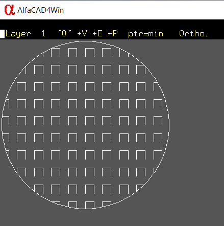
When enclosed area is selected, and program is waiting for indicating interior point, or changing settings in auxiliary menu /Hatching/, the pattern in actual scale, angle, color and line width is shown in the sample circle next to the crosshair cursor. This helps to check the parameters before executing the hatching procedure.
Terminology
Before explaining how to define hatch patterns (patterns), is necessary to define the necessary terms.
Pattern consists of one or more pattern lines (the number of lines is unlimited).
Each pattern line is part of a line family . The line family is created by generating the next line, shifted in parallel by a given increment from the previous line, in both directions from the baseline.
The delta_y size defines the spacing between family members (measured perpendicular to the line).
The delta_x value defines the displacement of line elements along the line representing the family element, and is applicable only for dashed lines.
A pattern line, considered as part of a line family, can be thought of as an infinitely long, invisible straight line over which a pattern defined by a definition is superimposed.
The process of pattern filling is to take successive pattern lines from the definition and spread them according to the rules above into an unlimited family of parallel lines.
In the filling process, AlfaCAD checks if there is an intersection of the pattern lines taken from the definition with the objects marked as the boundaries of the enclosed area.
Correct pattern of neighboring areas filling is ensured due to the fact that each line family is generated from the starting point specified in the definition. Each hatch pattern is defined by one or more line types (patterns). This allows you to create almost any conceivable hatch pattern.
Hatch Patterns with dashed lines
Patterns with dashed lines are created by adding fields that define the length of the line segment at the end of the line definition. If the number in the field is positive, it means a segment with a given length, and if the number is negative, a gap is generated. The pattern is generated from the starting point of the first segment and repeated cyclically.
A field with a value of zero defines a point (minimum length segment).
In one line, you can define a
segment with a maximum of six segments and gaps.
The previous
example can be modified in such a way that the program draws dashed
lines with a length of each 0.5 mm dash with 0.5 mm intervals at an
angle of 45°, keeping the distance between the lines 0.5 mm:
HATCH = 1;
hatching at an angle of 45 ° with dashed lines
45, 0, 0, 0, .5,
.5, -.5
The pattern differs from the previous one only with the addition of fields defining the dashed line segment. Leading zeros before the decimal point may be omitted in the definition.
This pattern can be modified by requesting hatching with dashed lines, the pattern of which consists of a dash 0.5 mm long, gaps 0.25 mm long, dots and another gap 0.25 mm long:
HATCH = 1;
hatching at 45 ° with dashed lines
45, 0, 0, 0, .5, .5, -. 25.0,
-.25
The effect of the delta_x parameter is shown in the following example:
(delta_x = 0) PATTERN1 = 1; delta_x with a value of 0
0, 0, 0, 0, .5, .5, -.5
(delta_x = 0.5) PATTERN2 = 1; delta_x with a value of 0.5 mm
0, 0, 0, .5, .5, .5, -.5
In the second case, the elements
in the next line are shifted by 0.5 mm parallel to the X axis.
In
all the examples so far, the patterns in which the base point
<x_start,
y_start> was the
point <0,
0> were
considered .
This means that the pattern line passes through this point and that
the line pattern segment started at this point.
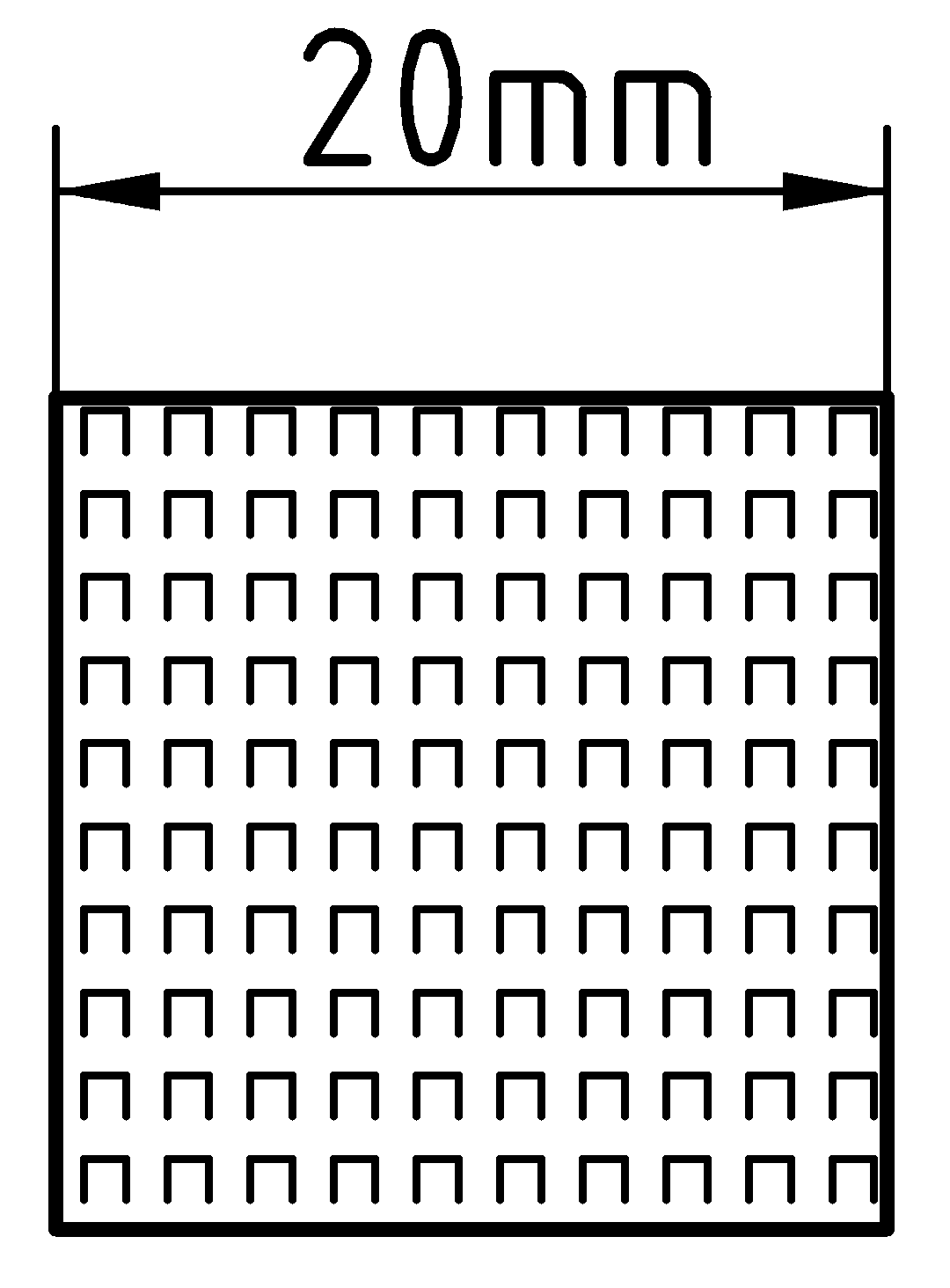
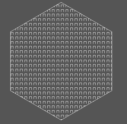
When composing more complex hatch patterns, it often becomes necessary to specify the starting point, distance, and sequence of segments and gaps separately for each defined line. So if there is a need to define the filling pattern in the form of a checkerboard of "open" squares resembling inverted U letters, where each basic element will consist of a vertical line on the left side, a horizontal line and a vertical line on the right side - as in the image below:
the pattern should be defined as follows (the assumed length of dashes is 0.5 mm, the distance between the segments is 1 mm):
U-LETTERS =
2; open squares
90, 0, 0, 0, 1, .5, -.5
0, 0, .5, 0, 1, .5,
-.5
270, .5, .5, 0, 1, .5, -.5
The first line defines a dash
drawn from the bottom up, starting at point <0.0>
.
The second dash begins at the
end point of the first dash, hence the base point is shifted to <0,
0.5> .
The third
line starts at <0.5,
0.5> . The third
dash can also be defined differently:
90, .5, 0,
1, .5, -.5 or
270, .5, 1, 0, 1, -.5, .5
The user can enter the angle of rotation of the pattern in relation to the global coordinate system. The standard patterns are designed in such a way that the hatch lines are parallel (for the "XXXXX" pattern also perpendicular) to the global X axis. To generate diagonal lines, specify a rotation angle other than zero (usually 45°).
Rotation angle can be also changed easy before inserting interior point (when hatch pattern sample is visible) pressing one of the following keys:
{PgUp} rotates +3°
{PgDn}
rotates -3°
{Home}
rotates +45°
{End}
rotates -45°
Scale specifies a factor that increases (decreases) the hatch pattern from the basic scale.
Changing the scale of the drawing or units in the / Parameters / main menu option does not affect the scale of the hatch pattern. Similar to texts, hatch pattern is a symbolic object, and as such is defined in [mm] related to the printing in scale 1.0, so all dimensions are simply expressed in [mm], similar to text height.
Base point specifies the offset value of the pattern starting point relative to the pre-defined base point.
If the adjacent areas are filled with the same pattern, in many cases it is important that the pattern lines are properly aligned with each other.
AlfaCAD provides automatic alignment of hatch lines of adjacent or disjoint areas by generating them relative to a common reference point (point <0.0> ). Changing the base point parameter allows you to move the hatch pattern to highlight the separability of different areas.
This parameter applies only to standard hatch patterns (/////, XXXX) and determines the distance between the individual lines that make up the pattern (this distance is expressed in millimeters related to the scale of drawing the drawing sheet on the printer and plotter). The distance is multiplied by the " Scale " parameter .
Creating sample block is easy, doesn't need any extra setup, and let user to extend own pattern library completed with useful visualization of the patter during hatching procedure.
 First,
import block sample.axx from Patterns folder.
First,
import block sample.axx from Patterns folder.
This is simple block containing just a circle, but of the proper size, with the base point on the top left.
Place that block in the top left corner of the drawing. It will be easy later on to replicate proper location of base point of modified block, for new hatching pattern sample.
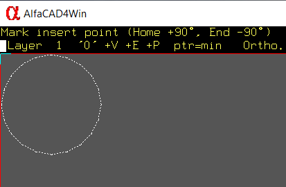
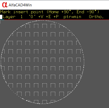
Now
fill the circle with newly created pattern, in our example U-LETTER
pattern. After selecting the circle as enclosed area for hatching, in
auxiliary menu in option / Pattern / select newly created pattern:
“U-LETTER”
Because pattern sample block doesn't exist yet,
instead you will see the sample of standard hatching. Indicate the
inside of the circle.
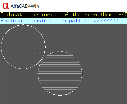
The circle will be filled with new pattern.
In function / Blok / / Export / select filled circle (using “window” or “cross” option) then indicate base point in the same point, so top left corner of the drawing.
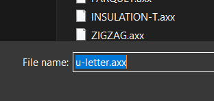
In the select file dialog window type the name of the file identical with the name of the pattern, with file extension “.axx”, so in our example: u-letter.axx
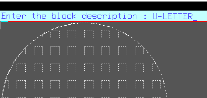
Enter to suggestive description (the best is just a name of the pattern, so U-LETTER
Enter empty block type, it is not needed.
The new hatching pattern sample block is created.
 When
you next time will use new patter for hatching, the sample block will
stick to the crosshair when you will indicate the point inside
enclosed area.
When
you next time will use new patter for hatching, the sample block will
stick to the crosshair when you will indicate the point inside
enclosed area.
Once it is done, the area will be filled with hatching pattern.
After calling the function / Hatching / , the program is waiting for selecting objects that make up a closed area, displaying the message: <Indicate hatch boundaries> .
After selecting the objects, the program waits for the indication of the point inside the area, displaying the message: <Indicate the inside of the area> .
Indication of a point inside the area may be preceded by calling the auxiliary menu and making a correction of the function parameters in the field of pattern name (type), rotation angle, scale, base point coordinates, distance (for standard patterns).
Shortcut keys {Home} for +45°, {End} for -45°, {PgUp} for +3° and {PgDn} for -3° can be used too.
After selecting a point inside a closed area, a filling block is generated.